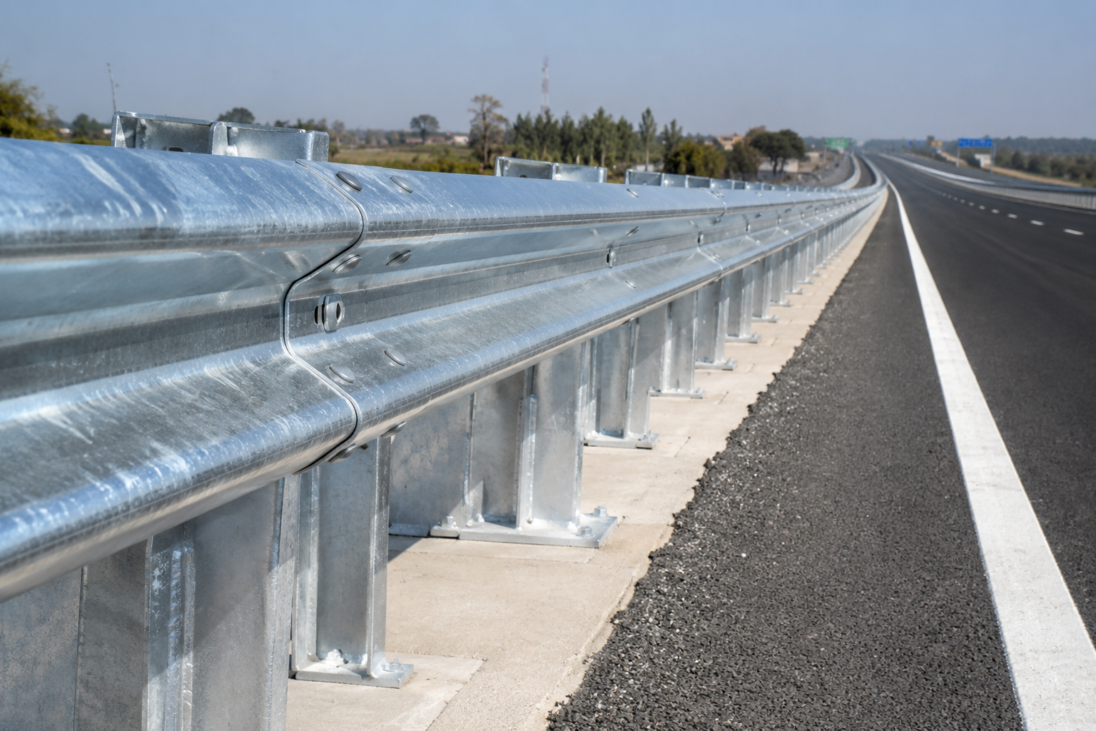
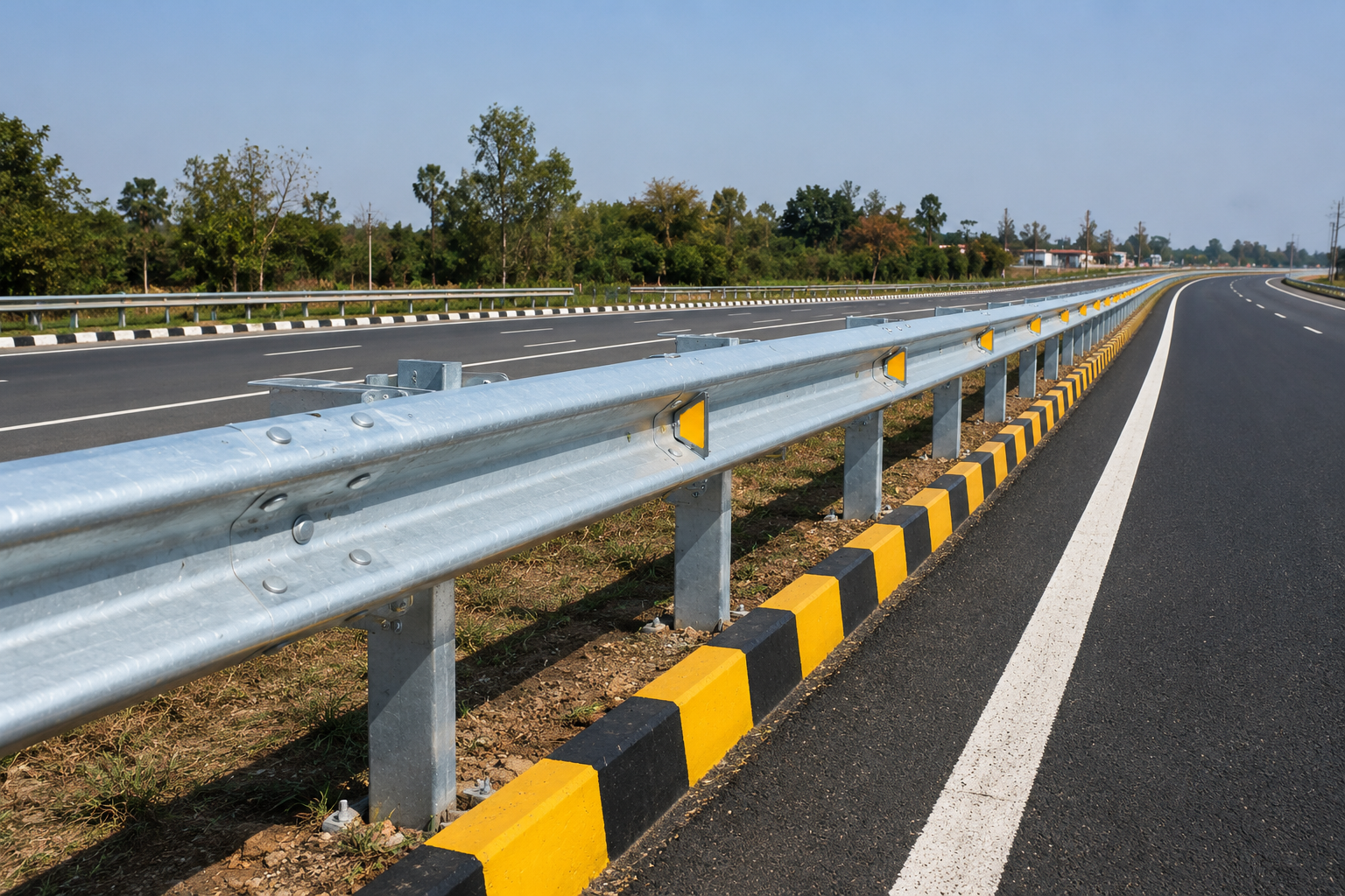
On Indian National Highways and Expressways, one of the most hazardous roadside configurations occurs where an approach embankment guardrail terminates at a bridge, culvert, or flyover structure. While the roadside barrier is typically a semi-rigid steel W-Beam or Thrie-Beam system designed to deflect dynamically between 0.8 m and 1.5 m upon impact, the bridge railing is almost universally a rigid Reinforced Cement Concrete (RCC) wall or cast-in-place concrete parapet designed for zero dynamic lateral deflection.
When an errant vehicle impacts the flexible guardrail run directly adjacent to the bridge interface, the abrupt jump in lateral stiffness causes the steel rail to pocket. As the vehicle deflects the flexible steel rail, it strikes the exposed, unyielding blunt nose of the concrete bridge parapet — resulting in catastrophic vehicle snagging, severe deceleration spikes, or vehicle rollovers. To eliminate this deadly failure mode, Indian Roads Congress guideline IRC:119 (Guidelines for Traffic Safety Barriers) and MoRTH Section 800 (Clause 810) mandate a fully engineered, crash-tested stiffness transition. Below is a practical technical guide from Metal Beam Barriers on specifying and detailing barrier transitions for highway structures.
1. Vehicle Pocketing vs. Snagging: Why Abrupt Stiffness Steps Fail
To understand transition engineering, project engineers must look at how impact energy travels through a barrier system:
- Vehicle Pocketing: Occurs when the barrier rail deflects excessively upstream of a rigid fixed object. The vehicle forms a lateral "pocket" in the steel beam, guiding the vehicle head-first into the downstream concrete abutment rather than redirecting it smoothly along the travel corridor.
- Vehicle Snagging: Occurs when vehicle components (such as the front tire, bumper assembly, or wheel hub) catch on an unyielding structural element, such as an exposed concrete nose, an intermediate stiffening post, or a poorly designed connection bracket. Snagging generates extreme longitudinal deceleration forces that fail the Acceleration Severity Index (ASI Class A/B) limits defined in EN 1317 and AASHTO MASH benchmarks.
Under IRC:119, an effective transition must provide a smooth, continuous, and progressive increase in lateral stiffness from the flexible approach rail to the rigid parapet.
2. Three Structural Steps to Build Progressive Lateral Stiffness
A compliant transition zone spans 15 to 25 metres upstream of the bridge parapet and achieves progressive stiffness through three coordinated engineering interventions:
| Transition Zone Segment | Typical Length & Geometry | Engineering Intervention & Stiffness Control | Reference Standards |
|---|---|---|---|
| Zone 1: Rail Profile Transition (W-Beam to Thrie-Beam) | 3.81 m transition panel | Replace standard 312 mm W-Beam with an asymmetrical cold-rolled W-to-Thrie transition piece, increasing beam depth to 506 mm to increase cross-sectional strength. | IRC:119, MoRTH Clause 810 |
| Zone 2: Post Spacing Reduction & Nesting | 8.0 m to 12.0 m prior to bridge | Reduce standard post spacing from 2.0 m down to 1.0 m, and finally 0.5 m directly adjacent to the concrete. Double-nest the 3.0 mm Thrie-Beam panels (placing two layers of steel beam together) to double the sectional moment of inertia. | IRC:119 Table 4, EN 1317-2 |
| Zone 3: Structural Terminal Anchor to Concrete Parapet | Terminal shoe / anchor bracket | Fasten the nested Thrie-Beam directly to the face of the RCC parapet using heavy-duty high-tensile galvanised anchor bolts (Class 8.8) and a cast-in-place or chemically anchored terminal transition shoe. | IRC:119 Section 6.4, MoRTH Section 800 |
3. Four Crucial Audit Checkpoints for Transition BOQ Compliance
Independent Safety Auditors and NHAI Safety Consultants regularly flag sub-standard transitions during pre-opening audits. When reviewing site execution and BOQ submittals, inspect these four details:
- Chamfering and Recessing the Parapet Nose: The concrete parapet must be tapered or chamfered backwards away from traffic by at least 10:1 to 15:1 over the first 1.0 m to 1.5 m. The terminal steel shoe should tuck behind the chamfered concrete face so oncoming vehicle tires cannot snag on the metal edge.
- Post Foundation Rigidity Near Abutment Backfills: The last 3 to 4 steel posts before the bridge wing-wall sit in granular backfill behind the abutment, which frequently exhibits lower lateral soil resistance. In these zones, posts must be extended in length (up to 2.0 m to 2.5 m embedment) or socketed into RCC grade beams.
- Zinc Coating Integrity on Transition Fasteners: High-tensile transition bolts, spacers, and custom terminal brackets must carry hot-dip galvanising matching MoRTH Section 800 norms (minimum 550 g/m² zinc coating mass) to prevent galvanic corrosion at the steel-concrete interface.
- Delineator Alignment: Install bi-directional retroreflective delineators along the transition face to ensure drivers visually track the narrowing shoulder clearance at night.
4. Frequently Asked Questions (FAQ)
Why can't contractors simply bolt a standard W-Beam directly to a concrete bridge wall?
A standard W-Beam has high lateral flexibility and a 312 mm profile. Bolting it directly to a rigid concrete wall creates a drastic stiffness discontinuity. During an angled vehicle collision, the beam bows inward, causing the vehicle's front quarter to spear directly into the blunt concrete corner.
What is a "nested" Thrie-Beam rail in transition design?
Nesting refers to placing one Thrie-Beam rail directly inside another, fastening them together with shared splice bolts. Nesting doubles the steel thickness from 3.0 mm to 6.0 mm along the final 4 to 8 metres approaching the bridge, drastically increasing bending resistance without requiring complex structural welding.
What post spacing should be specified approaching a bridge parapet under IRC:119?
Post spacing should be stepped down systematically: standard 2.0 m spacing transitions to 1.0 m for 4.0 metres, and then reduces to 0.5 m spacing for the final 3.0 to 4.0 metres directly before anchoring into the rigid parapet.
Request Factory-Certified Transition Components from Auroguard
Are you designing or procuring crash barriers for an upcoming NHAI, MoRTH, or State PWD highway bridge package? Metal Beam Barriers by Auroguard Private Limited manufactures hot-dip galvanized (550 g/m²) W-Beam, Thrie-Beam, W-to-Thrie transition panels, and structural terminal shoes engineered to IRC:119 and MoRTH Section 800 standards in Kolkata. Send your structural drawings and chainage schedule to hitesh@auroguard.co.in or sales@auroguard.co.in, or call/WhatsApp +91 90510 39176 for immediate factory support.